FULL HANDBOOK
Chapter 1: Industry Overview
Chapter 2: Geology & Site Selection
Chapter 3: Drilling & Blasting
Chapter 4: Excavating & Loading
Chapter 5: Hauling
Chapter 6: Crushing & Hydraulic Breaking
Chapter 7: Screening
Chapter 8: Washing & Classifying
Chapter 9: Conveying & Material Handling
Chapter 10: Loadout & Weighing
Chapter 11: Safety & Health
Thickeners & Filter Presses
When operating a wash plant, environmental regulations typically require you to contain the effluent of the silt/clay-laden dirty washwater on your property. You will have a lot of washwater, but because it may contain 10 percent ultra-fine solids, it can’t be used back into your plant – unless you can somehow separate the silt and clays from most of the water.
A thickener allows a wash plant to reclaim up to 85 percent of the water for immediate use back into the wash plant. Concentrated mud discharging typically at 40 percent solids content also reduces the space required for tailings containment.
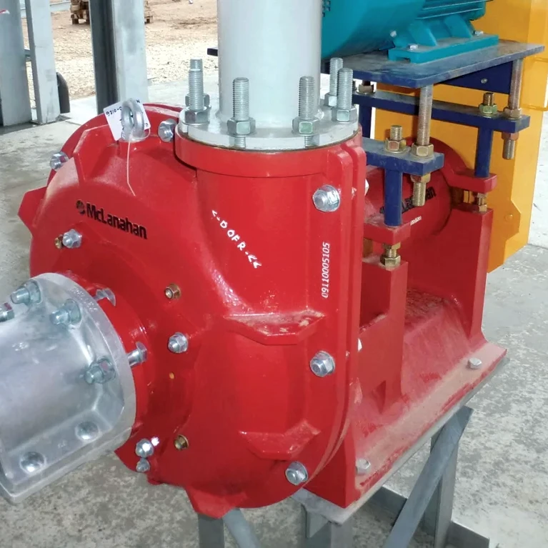
Pumps
Pumps are part of the equation with washing and classifying operations, as well. The ones used in mining and aggregate applications are subject to some of the harshest and most demanding conditions on earth.
From dewatering to mineral extraction, pumps perform efficiently in difficult conditions and for long hours. It’s important to select the most appropriate pumps for each specific application.
Several factors will dictate pump selection and configuration. The first step is to define the overall system objectives, considering uptime requirements, maintenance spending targets and energy efficiency requirements. Once these have been established, the process of choosing a pump can begin.
Start by choosing a pump type that is suitable, given your application and system objectives. Certain pump types are more energy efficient than others, have different physical footprints, require different maintenance frequency and have different price points.
Definition
Pump: A mechanical device that moves water or slurry through a system; critical in washing and classifying operations.
&uuid=(email))
Size and configuration
Once a type is selected, the pump must be sized and configured for the application. To do this, engineers must define the flow rate or volume of water passing through the pump per unit in time, based on the application’s requirements.
Engineers must then determine the static head and friction loss of the system. The static head is the height of a column of water that would be produced at a given pressure. Calculating the static head identifies the internal energy of a fluid owing to the pressure exerted on it from the pump. Friction loss is the reduction of static head that occurs due to viscous effects generated by the size and surface of the pump and flow path.
Friction loss occurs throughout the entire system and must be accounted for. Narrow corners and valves that impede flow create high friction loss.
Many pump manufacturers offer selection software that takes the operating parameters (i.e., flow rate and head) and generates pump configurations with their corresponding best efficiency points. This enables selection of the most hydraulically efficient pump size based on the system’s requirements.
Software can also help with net positive suction head and other selection considerations, such as the environmental conditions the pump will be working in. These determine the best motor enclosure, base plate (where applicable), paint and other options.
For mining applications, it is important to select a pump that is compatible with the media being transported. Some pumps are specifically designed to handle slurries and can be constructed with hardened metal components or use rubber-lined casings to reduce abrasion. They can be used to move mixtures of liquid and suspended solids in a broad array of applications such as mine drainage, dredging of settling lagoons and pumping of drilling mud.
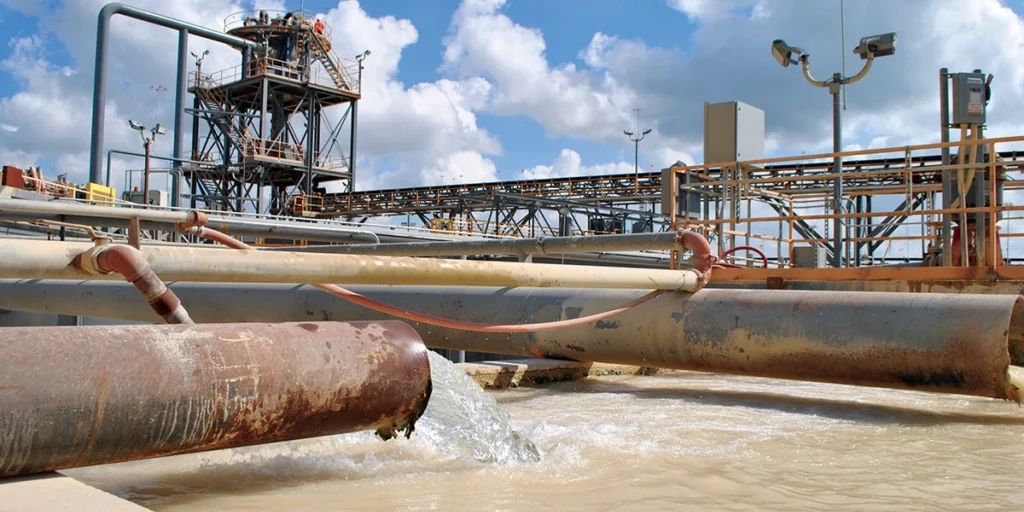
Recycling Wash Water
Maintaining clean wash water is essential to operations with a wet process.
Producers reusing dirty water in their wash system are essentially putting all the dirt, debris, clay and fines back onto the product they’re trying to clean. At the same time, this causes wear, tear, clogging and buildup on equipment, water pipes and spray bars.
Fortunately, there are three methods of recycling and reusing wash water that producers typically follow: traditional settling ponds, ultra-fines recovery systems (UFRs) and clarification systems.
PRO TIP
Recycle wash water smartly: Ultra-fines recovery systems and thickeners reduce pond maintenance and water demand.

Settling ponds
While pumping dirty water to a settling pond is a simple concept, particles settle out naturally with time and gravity, allowing fresh water to float to the next level of the pond to be reused. The disadvantages, however, are space requirements and permitting restrictions that make it harder to establish ponds.
There are also evaporation issues and maintenance costs involved. The costs can be hefty when having to dig out sediments to ensure the needed depth for required settling.
On the plus side, settling ponds can work well for operations that have a larger footprint and can successfully use flocculants to achieve greater settling efficiencies.
UFRs
A UFR system, meanwhile, offers the advantage of removing a good portion of material down to a #400 mesh, keeping more fines out of the pond. This results in less digging during pond maintenance.
Additionally, a UFR provides a stackable material that can become a saleable product, resulting in minimized waste. Also, the water remains much cleaner and requires less processing before reusing it.
One of the downfalls of UFRs is an occasional situation where wastewater travels too far downstream in the pond, requiring additional flocculants to separate particles. In this event, enough larger particles are not present to stimulate the settling process.
The latter results in a “double dipping” during the process. Still, if a UFR can minimize the need to dig out the pond, a savings in operating costs can be achieved.
Definition
Flocculant: A chemical additive used to help fine particles clump together and settle out of wash water.
Clarification systems
Growing in use, clarification systems start with something as simple as a thickener or the use of a clarification tank.
No matter the option, clarification systems have space and flocculant requirements. Clarification systems are becoming more popular, though, as they’re less likely to incur permitting issues. They also allow operations to eliminate settling ponds.
Clarification systems discharge a sludge waste product that’s typically pumped to a designated area, where it must sit and dry. Sometimes, this waste product requires the use of filter or belt presses that pull out extra moisture, creating a solid, stackable cake that’s potentially used as a fill product.
The biggest drawback of a clarification system is the capital investment required. But, depending on the cycle time of the complete clarification system – which can create a bottleneck – it delivers extremely clean water back into the wash circuit.

Finding the right solution
Efficiency improves when optimizing all the equipment in the wash plant.
For example, if sand screws are not running properly, an operation may be washing valuable product and sending it to the pond. Conduct a thorough plant audit to evaluate the performance of each piece of equipment in the plant. Regular performance checks on each component prevent product loss and inefficiency.
Again, each wet processing operation is different, and the right solutions depend on parameters such as material type, moisture content, specification requirements, size of footprint, permitting restrictions, financial limitations, water rates, water availability and more.
Proper analysis by an experienced applications engineer is advised. Avoid cookie-cutter or one-size-fits-all equipment approaches. The best practice is to rely on highly targeted, customized solutions.
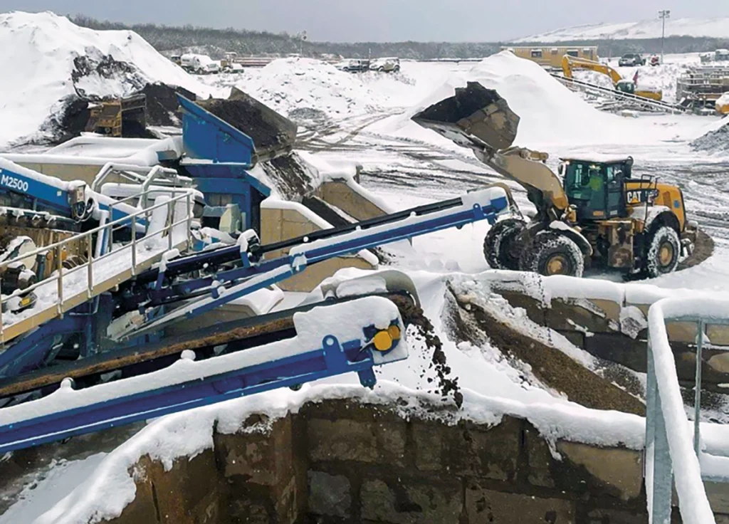
Winter Washing
Winter’s icy grip presents a unique set of challenges for wash plant operators in northern climates.
With effective planning, though, producers can protect their investments and ensure operations are ready for an efficient return to production come spring.
When it comes to plant maintenance, it is essential that any potential complication is identified and remedied quickly to protect an operator’s investment and ensure optimal performance – particularly during the coldest months of the year, when washing and classifying equipment is especially susceptible to the elements.
With planning and preparedness, operators can ensure the safe and efficient shutdown of a wash plant in winter and facilitate an efficient restart of operations in the spring.
SAFETY TIP
Protect against winter hazards: Drain standing water from tanks and pumps to avoid freeze damage and unsafe restarts.
&uuid=(email))
Five steps to follow
1. Water management. Effective water management as the cold weather sets in should be paramount for operators. It’s advisable to drain all standing water from tanks and pumps when plants are mothballed for the winter season. Otherwise, operators risk lines freezing and cracking, leading to a delayed and costly restart in the spring.
2. Insulate. The winter months can present unforgiving conditions, so consider insulation to protect pipes, valves and pumps. Ensure your control cabin is closed and, if possible, keep the internal heating on to protect the beating heart of your plant from plummeting temperatures.
3. Open valves. In addition to draining the system and, where possible, insulating pipes, valves and pumps, it’s advisable to keep valves open during winter shutdown. This will prevent any residual water from accumulating in the system.
4. Spray bars. Clean out spray bar nozzle heads, and ensure smaller pipework is free of debris such as silt and sands. Also, ensure spray bars receive adequate water pressure, and that the spray from nozzle fans is at the correct angle. This will allow operators to get more water onto the screen to ensure the product is getting the best washing treatment.
5. Safety protocols. Winter also poses safety concerns for plant operators. Consider refreshing and rehearsing your training procedures to ensure your teams are well versed in the appropriate safety protocols when working in the vicinity of a wash plant to avoid slips, trips and falls.
Proactive and preventive approaches to plant maintenance during winter months are essential for long-term efficiency and profitability, but unforeseen challenges can still arise despite the best-laid plans.
FULL HANDBOOK
Chapter 1: Industry Overview
Chapter 2: Geology & Site Selection
Chapter 3: Drilling & Blasting
Chapter 4: Excavating & Loading
Chapter 5: Hauling
Chapter 6: Crushing & Hydraulic Breaking
Chapter 7: Screening
Chapter 8: Washing & Classifying
Chapter 9: Conveying & Material Handling
Chapter 10: Loadout & Weighing
Chapter 11: Safety & Health
Use the page numbers to continue reading, or select a section / chapter above.