FULL HANDBOOK
Chapter 1: Industry Overview
Chapter 2: Geology & Site Selection
Chapter 3: Drilling & Blasting
Chapter 4: Excavating & Loading
Chapter 5: Hauling
Chapter 6: Crushing & Hydraulic Breaking
Chapter 7: Screening
Chapter 8: Washing & Classifying
Chapter 9: Conveying & Material Handling
Chapter 10: Loadout & Weighing
Chapter 11: Safety & Health
Attrition Scrubbers & Bucket Wheels
Attrition scrubbers, also known as attrition cells, are used to liberate deleterious material and remove them from competent aggregates.
They also liberate clays, reduce product turbidity and break apart loosely conglomerated clusters in frac sand plants.
Attrition scrubbers can be used in glass sand, frac sand, clay, and sand and gravel production, as well as in preparation of flotation feeds and reagent washing.
Attrition scrubbers produce a high-shear environment where particles scrub against themselves to scour their surface and liberate deleterious materials. All internal parts are completely rubber lined to maximize wear life and minimize maintenance time and costs of replacement parts.
The cells are typically fed by separators, hydrosizers or similar equipment that will prepare material at a high density and achieve the best scrubbing action possible.
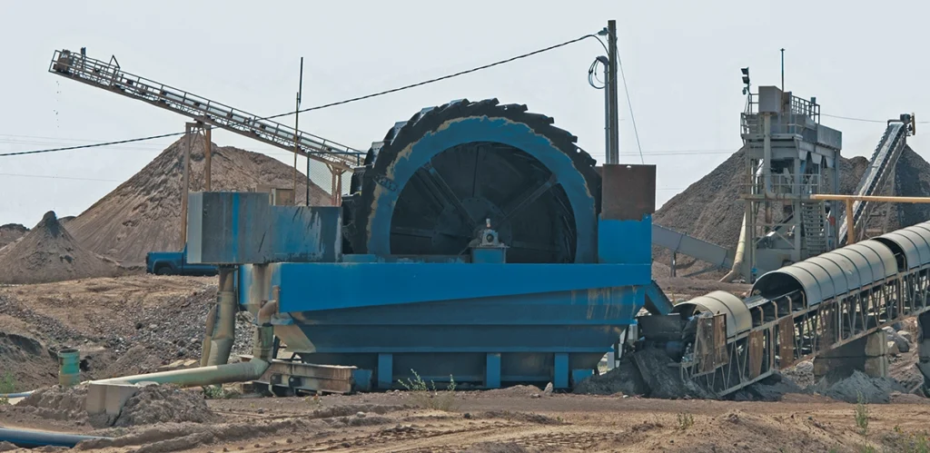
Bucket wheels are capable of capturing, desliming and dewatering sand, frac sand, waste fines, specialty sands and gravel from dredging and sand processing operations. They are typically engineered for high solids recovery with low power consumption.
Definition
Desliming: The process of removing very fine particles (slimes) from aggregate.
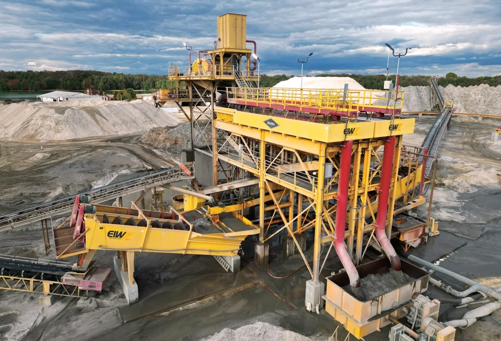
Classifying Tanks
Classifying tanks are widely used to process sand to spec. They remove excess water, classify sand by removing intermediate mesh sizes, retain finer mesh sizes and make multiple products from a single-feed material.
Classifying tanks are effective, low-maintenance units that produce one or more specification products. With either slurry or a dry feed, they handle sand-gradation swings in the average plant while producing concrete, asphalt and mason sand products with minimal waste.
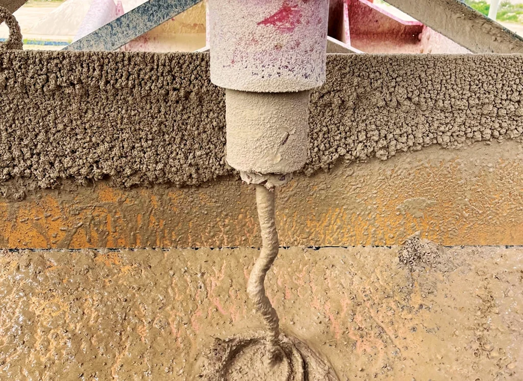
Sand classification is based on grain size settling rates. As water and material enter the feed end, coarser grains settle first while finer grains settle progressively down the length of the tank. At the top, hydraulic control mechanisms operate discharge valves at the bottom. Depending on the control system and product requirements, one, two or three valves may be located at each station.
Proper sizing of a classifying tank requires considering several factors, including water volume with the feed, tonnage capacity, number of desired end products and product specifications.
Consistency of feed material is also critical. Variations in raw composition can disrupt separation and affect product quality. Regular monitoring and adjustment of feed help maintain stable operations.
&uuid=(email))
Many modern tanks feature advanced PLC control systems that automatically adjust valve operations based on sensing paddle feedback. These controls improve classification accuracy, reduce operator intervention and increase overall efficiency.
Proper adjustment of sensing paddles and weirs is equally important. Leveling the weirs ensures accurate classification and silt removal. Raising side weirs and lowering the back weir allows finer particles to overflow, effectively removing minus 200-mesh material.
Paddle heights should be set high in the first stations to accommodate fast-flowing coarse sand and lower in later stations to ensure fine sand is discharged as a concentrated product rather than excessive water.
Routine maintenance is crucial for consistent operation. Valves and valve seats are among the most frequently replaced components. While many original parts are hard-cast iron alloys, polyurethane replacements often offer extended wear life. Valve rods, torque motor paddles and paddle rods should also be inspected regularly and replaced when needed.
Sand discharges from valves through downpipes into sectionalized collecting flumes, often fitted with elbows. Elbows handling coarse sand wear faster and require more frequent replacement than those handling finer material. While many tanks still use steel pipes and hard-iron elbows, thick-walled PVC pipes and polyurethane elbows are increasingly common due to their lighter weight, ease of replacement and durability.
Collecting flumes should be lined with AR steel, rubber or polyurethane to protect against abrasion. Liners should cover both the bottom and sides of the flume.
Valve openings are controlled by hydraulic cylinders connected to valve rods, powered by a self-contained hydraulic unit. Hydraulic fluid and filters should be replaced periodically according to manufacturer recommendations. For tanks idle during seasonal shutdowns, the hydraulic reservoir should be checked for condensation buildup, with water drained and fluid levels maintained.
Electrical systems, wiring and hydraulic lines should also be inspected to ensure proper function and to prevent hazards such as grounding issues or leaks. The control enclosure atop the sand tank, which houses hydraulic cylinders, torque motors, solenoid valves, wiring and hydraulic lines, should be kept clear of accumulated sand to prevent component failure.
If the tank is equipped with a rising current recirculating pump, the impeller should be inspected for wear and replaced when needed. V-belts driving the pump and bearing lubrication also require regular attention in line with manufacturer specifications.
Although classifying tanks may appear complex, they are straightforward to maintain with routine inspections and scheduled service. Consistent maintenance reduces downtime, ensures reliable product output and extends equipment life, making classifying tanks a cost-effective investment for aggregate producers.
Hydroclones
Hydrocyclones are widely used for fines removal, classification and dewatering.
With no moving parts, they can be installed in a variety of ways. Some are mounted on towers or other structures and positioned away from processing equipment.
To achieve proper performance, hydrocyclones must be fed via a pumped slurry in a consistent percentage-of-solids range, as well as at the pressure specified by the supplier. With these requirements, capital and operating costs – including electric power – should be reviewed when considering hydrocyclones.
Hydrocyclones, also called “cyclones,” separate particles by size and density using centrifugal force to accelerate the settling rate of solids. They are cylindrical-conical devices with one entrance and two exits, consisting of a feed box, feed inlet, vortex finder, optional feed box extension, cone sections and a spigot.
Slurry is fed under pressure, causing it to swirl inside the cylindrical feed box. The swirling motion produces a vortex and an air core along the cyclone centerline. Coarse, heavy particles are pulled outward in a helical motion toward the underflow discharge at the bottom, while finer, lighter particles are pulled upward in a helical motion toward the overflow discharge at the top.
Performance specifications vary by application. Hydrocyclones may be evaluated by the particles reporting to the underflow or those reporting to the overflow. For example, in C-33 concrete sand production, underflow performance is critical and measured by the cut point. In mineral or hard rock applications, separation efficiency is often a better indicator of cyclone performance, with overflow quality being more important than underflow.
Cyclone performance is influenced by six key factors:
1. Size. Hydrocyclone size plays a major role in performance. Each particle migrates to a position where centrifugal force equals drag force. If centrifugal force is greater, the particle exits through the underflow; if drag is greater, it exits through the overflow. This balance point is known as the D50 or cut point. Smaller cyclones generate stronger centrifugal forces, producing finer cuts. Larger cyclones generate weaker forces, producing coarser cuts. For primary sand production and desliming, larger cyclones are recommended, while fines recovery typically employs smaller or multiple cyclones.
2. Flow rate. Flow rate affects the internal pressure of the cyclone. Lower feed pressure produces a coarser cut, while higher feed pressure produces finer separation. Pressure can be adjusted by changing pump speed. Slowing the pump decreases flow and pressure for a coarser cut, while increasing speed raises both for a finer cut.
3. Inlet area. The inlet size determines capacity. Larger inlets allow higher throughput at the same pressure. Adjusting inlet area can increase or decrease capacity without altering pressure.
4. Vortex finder diameter. The vortex finder extends into the feed box and controls separation. A larger diameter allows more material into the overflow, resulting in a coarser cut, while a smaller diameter produces finer separation. Larger vortex areas reduce internal pressure, sending more material to the overflow. Smaller areas increase pressure, sending more to the underflow.
5. Underflow diameter (apex). The apex must be matched to tonnage. If too small, the air core cannot form properly and the underflow will “rope,” indicating poor operation. If too large, excess air, water and fines pass into the underflow, negatively affecting the cut point. A smaller apex reduces bypass and increases underflow concentration, while a larger apex should be used if coarse particles appear in the overflow or underflow roping occurs.
6. Length. Cyclone length affects separation by determining residence time. Longer cyclones provide more time for particles to separate, producing finer cuts. Shorter cyclones reduce residence time and make coarser cuts. Length is influenced by cone angle and optional feed box extensions. A 10-degree cone angle creates a longer cyclone, while a 40-degree angle produces a shorter one.
Hydrocyclone performance should be evaluated at the feed, overflow and underflow. By comparing results to application goals, operators can adjust size, pressure and components to optimize separation.
&uuid=(email))
Definition
Dewatering screen: A vibrating screen designed to discharge sand or fines with minimal moisture content.
Dewatering Screens
Developed in the South African minerals processing industry about 40 years ago, dewatering screens have been used in North America for more than 30 years because of their compact footprint and high-percent solids content discharge.
Stationary, skidded and portable units have become commonplace in the industry.
First widely used in dewatering a hydrocyclone underflow where plus 400 mesh solids can be recovered, they have also been used for more than 25 years to dewater a fine material screw washer discharge that results in a drip-free washed sand.
Using rubber or polyurethane liners and screen media and, in most designs, having dual-enclosed, low-horsepower vibrating motors, dewatering screens provide a reduced operating cost per ton of production device for many wet processing plants.
Varying dewatering screens are on the market. A properly designed dewatering screen discharges the driest washed sand product of any dewatering device commonly used. Additionally, less space is required than other options.
Depending on the slurry of the sand feed and the percentage of solids in the sand flow, these units often require a sump, pump and one or two hydrocyclones to partially dewater the slurry and allow the screen to adequately perform. The capital cost of a dewatering screen system is often more than two times other choices, and the electricity cost is often up to three times more.
FULL HANDBOOK
Chapter 1: Industry Overview
Chapter 2: Geology & Site Selection
Chapter 3: Drilling & Blasting
Chapter 4: Excavating & Loading
Chapter 5: Hauling
Chapter 6: Crushing & Hydraulic Breaking
Chapter 7: Screening
Chapter 8: Washing & Classifying
Chapter 9: Conveying & Material Handling
Chapter 10: Loadout & Weighing
Chapter 11: Safety & Health
Use the page numbers to continue reading, or select a section / chapter above.