FULL HANDBOOK
Chapter 1: Industry Overview
Chapter 2: Geology & Site Selection
Chapter 3: Drilling & Blasting
Chapter 4: Excavating & Loading
Chapter 5: Hauling
Chapter 6: Crushing & Hydraulic Breaking
Chapter 7: Screening
Chapter 8: Washing & Classifying
Chapter 9: Conveying & Material Handling
Chapter 10: Loadout & Weighing
Chapter 11: Safety & Health
Pulley Lagging
One time-consuming job that has the potential to cause unplanned work stoppages is replacing conveyor drum pulleys with worn-out lagging.
The difficulty of replacing these pulleys varies greatly depending on several factors. The position on the conveyor, accessibility and pulley size are a few things that determine how difficult the job is. The time required on the job can range from a couple of hours in the easiest changeouts to a day or more in the most difficult cases.
It is often assumed that worn-out lagging is no big deal and that conveyors can function fine even if the lagging is worn through to the steel pulley rim. In some instances, this may be true. But lagging may play a more crucial role in conveyor performance than is often realized.
Lagging provides several benefits, including increased traction to drive the belt and less material buildup in sticky applications. When the drum is lagged, it protects the steel rim from wear.
&uuid=(email))
If too much rim wear occurs, it can cause a sudden catastrophic failure. Also, it can be difficult to recognize just how much rim wear occurs in these instances.
As lagging in the center of the pulley wears down, it diminishes pulley crown. This diminished crown has an impact on how well the conveyor belt tracks.
The challenge, then, becomes how to make the lagging last longer so changeouts are less frequent. The tire industry struggles with similar challenges, and conveyor component manufacturers are benefiting from what they’ve learned.
Tire manufacturers have spent a lot of time and effort developing rubber compounds that are more resistant to wear, punctures and tearing while maintaining traction levels. By implementing some of this technology, special abrasion-resistant (AR) lagging compounds can be selected that can have a dramatic impact on pulley life.
Testing has shown results of up to double the life of traditional lagging compounds in high-wear applications. Producers who deal with some of these highly abrasive materials may get used to dedicating considerably more time to maintenance operations than typical producers.
Still, the financial impact becomes clear when producers start assigning costs to accelerated wear. For instance, assume an abrasive material is being crushed and it is typical to only get 18 months of service life from standard styrene-butadiene rubber lagging, whereas AR lagging extends that service life to 36 months.
In three years, a producer would have consumed two standard lagged pulleys but only used one of the AR lagged pulleys. That is one entire changeout that was not necessary.
Let’s say this pulley requires eight hours to replace with a crew of three people for a total of 24 hours. The AR lagging material change would save eight maintenance hours each year. When multiplied by the total number of lagged pulleys in an operation, the savings add up.
Overcoming pulley slippage
Conveyor drive pulleys must maintain belt traction to operate properly.
When traction is compromised, production suffers and pulley or belt damage can occur.
Traction problems are often a symptom of material overload, poor maintenance, component wear, component aging, contamination, inclement operating conditions and poor design. But with an understanding of the variables contributing to drive traction, most issues can be remedied quickly and some misconceptions about drive traction can be avoided.
Design handbooks and industry standards use versions of the Euler-Eytelwein formula, also known as the capstan equation, to estimate drive traction.
In most cases, a basic understanding of the formula’s variables is sufficient and a deep dive into equations isn’t necessary. The most significant variables are belt angular wrap on the pulley, coefficient of friction between the contact surfaces, and proper slack-side belt tension. Pulley diameter is not a significant variable, as test results illustrate.
In general, if one or more of these three variables isn’t right, then drive traction may become an issue. To correct traction problems, it is important to investigate all three of the key variables because they are interrelated. Focusing on just one or two may not solve the problem.
Also, the interaction between rubber-covered fabric belts and lagged pulleys is more complex than handbooks and industry standard equations consider. Rubbers and belt materials are elastic and exhibit significant stretch under load. Modeling of these interactions is an area of ongoing industry research. Fortunately, a solid understanding of the concepts suffices in solving most dilemmas.
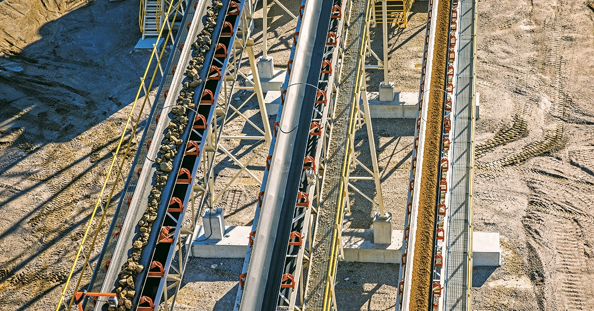
1. Belt wrap
Belt wrap, which is usually measured in degrees, is the amount of angular contact the belt makes as it wraps around the drive pulley.
In a simple two-pulley conveyor, the belt wraps around half of the pulley – which is 180 degrees. In more complex conveyors, it is common to use additional pulleys and increase the belt wrap to 210 degrees or more.
The belt applies a pressure on the pulley, resulting in a force that pushes into the pulley surface. The force is related to the belt tension at the point of contact and is highest on the tight side of the drive pulley and lowest on the slack side of the drive pulley.
Between these points, the force transitions throughout the arc of contact. Increasing the belt wrap increases the total force at the contact surface, resulting in increased traction.
In most cases, increasing the pulley diameter does not provide the same traction improvement as increasing the belt wrap angle. This is because the available driving force remains largely unchanged when the pulley diameter grows, due to the corresponding reduction in pressure.
While making the drive pulley diameter larger typically won’t improve traction, adding a snub pulley to increase the belt wrap beyond 180 degrees is a common way to improve traction.
2. Friction
Friction between the belt and pulley is necessary for traction to occur.
Designers may use a bare steel, rubber-lagged or ceramic-tiled pulley surface to achieve the level of friction they desire. Steel surfaces have the lowest friction coefficient; rubber laggings are higher, and nubbed ceramic-tiled surfaces tend to have the highest friction.
Additionally, belt cover properties may be changed to improve friction. Even well-designed conveyors can have traction problems if intended friction is reduced by damage, wear, rubber aging, contamination and material buildup.
Most of the friction coefficients published are an approximation of the friction factor for when the onset of global drive slip will occur, with a safety factor built in. In reality, a portion of the belt wrap angle is always slipping, and the remaining wrap is static between the belt and pulley surfaces.
In most cases, the traction of a drive pulley stays the same regardless of the diameter. As diameter is reduced to extremely small values, the friction factor becomes lower at the higher contact pressures.
In most cases, the traction of a drive pulley stays the same regardless of the diameter. As diameter is reduced to extremely small values, the friction factor becomes lower at the higher contact pressures.
As more power is transferred, the slipping portion of belt wrap increases until the entire belt wrap is slipping, and the maximum power is being transferred. Attempting to use more power results in global drive pulley slippage.
While not intuitively obvious, the slipping portion of the belt wrap is what actually transfers power. Handbooks and industry standards typically assume the coefficient of friction is constant in a given situation, but this isn’t always the case, as traction can decrease at smaller pulley diameters.
&uuid=(email))
3. Slack
It is also important to maintain sufficient slack-side belt tension to avoid traction issues.
Conveyor designers must select a slack-side tension range when selecting pulleys, idlers, bearings, belting and frame components. Maintenance personnel should keep the conveyor tensioned within this intended range.
Too much slack-side belt tension and component failures may occur. Too little slack-side tension and drive slippage may occur.
Automatic or gravity take-up systems are intended to improve control of the slack-side belt tension. But even these systems require maintenance because hydraulic or pneumatic settings can change, rails and slides can be damaged or contaminated, and bearings or sheaves can stiffen and seize.
Manual take-ups create additional challenges to control slack-side belt tension. They often have no simple way to quantify what tension is being created, so the belt tension can vary significantly when adjusted. Quantifiable estimates can be made using belt stretch and belt sag methods, but they tend to be cumbersome – and most maintenance personnel rely on feel and experience.
In addition, slack-side belt tension varies significantly during operation due to belt stretch under load. When the drive applies power to the belt, the carrying portion of the belt will stretch. Since manual take-ups stay fixed during operation, the only place this stretched belt can go is to the slack side of the conveyor.
This leads to increased slack-side belt sag and reduced slack-side belt tension. This can result in a stationary belt being set with what appears to be ample slack-side tension yet, when stretched under load, having the slack-side belt tension reduced to levels that allow for drive slip and traction issues.
Maintaining traction and avoiding drive pulley slippage is important to maximize conveyor production and avoid damage to conveyor components. A basic understanding of the variables affecting traction is essential to confidently diagnose and correct drive slip issues.
Belt wrap, friction and slack are interrelated. A focus on fewer than all three can result in significant effort and expense without tangible improvement.
Industry field engineers will look at the belt wrap angle on the drive pulley, the friction coefficient of the pulley and belt contact surfaces, the condition of the pulley and belt contact surface, environmental factors that might be affecting traction, and the slack-side belt tension when the conveyor is stationary and running at peak load.
Weighing all factors, a technician can create a solution to traction problems that is simple, economical and effective.
PRO TIP
Pair magnets with detectors: For tramp metal control, combine electromagnets with downstream detectors to improve capture efficiency and equipment protection.
Other Components
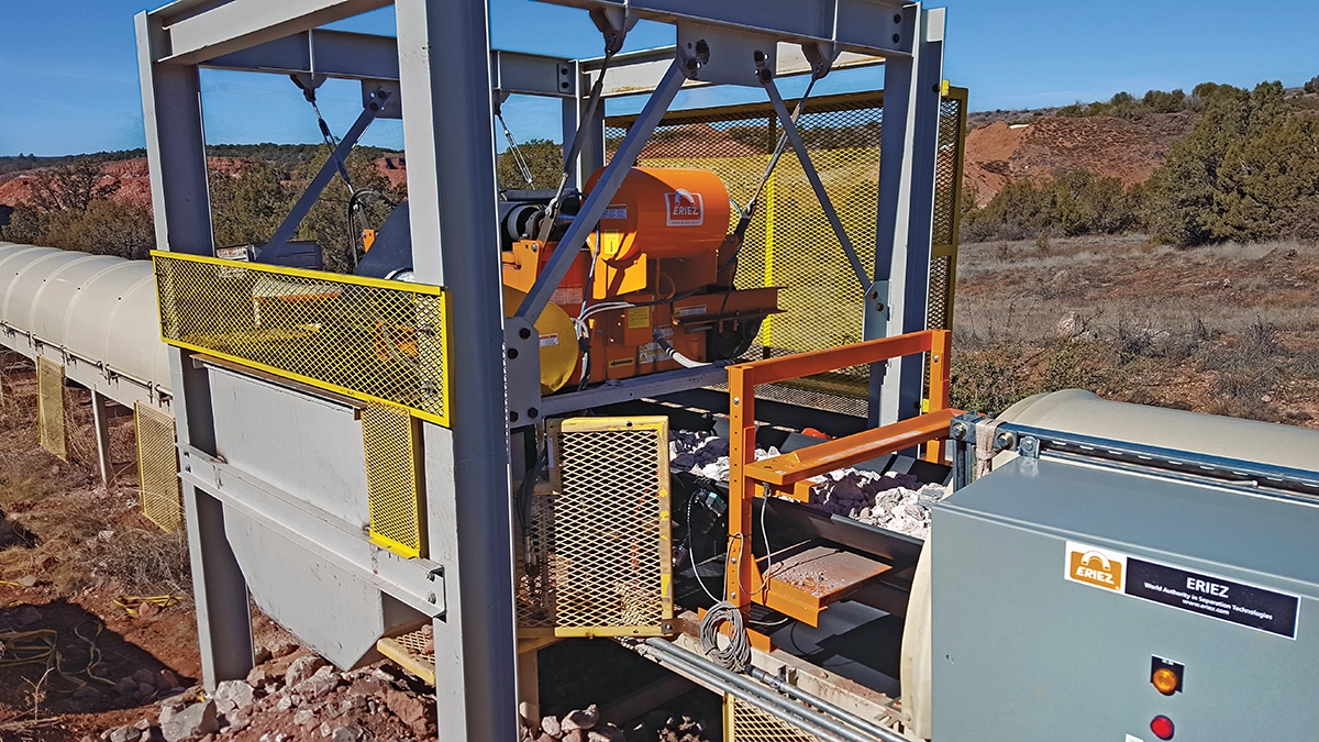
Electromagnets
Managing tramp metal throughout a conveyor system is part of the job of quarry operators everywhere. One way to capture such material is with a magnet. An even better way to prevent metal from damaging a production system is to pair a magnet with a metal detector.
For quarry operators, electromagnets are a good starting point to best manage tramp metal. Determining which type of magnet is best for the many applications in aggregates, however, is easier said than done.
Several factors rise above all others when selecting an electromagnet for a quarry application: belt width, belt speed, idler degree and burden depth are among those. The typical size and type of metals targeted for removal is also critical information for equipment vendors – and the metal’s shape matters, too.
Another metric that matters with magnet sizing is suspension height. Suspension height is determined by the burden depth, which is the depth of the product on the belt. The magnet suspends over the top of the product burden, attracting metal out of the product flow and discharging it away from the magnet or manually removing it.
Suspension height is the factor that matters most when installing an electromagnet. But where a magnet resides along the conveying system is important, as well. Perhaps the most effective location to install a magnet is over the head pulley.
While an electromagnet should capture the majority of tramp metal in a production system, a metal detector positioned downstream can serve as a security blanket.
Keeping a magnet free of debris is vital to its performance, as well. But keeping a manual-cleaning permanent magnet clean can be more of a chore for producers than they originally anticipate.
FULL HANDBOOK
Chapter 1: Industry Overview
Chapter 2: Geology & Site Selection
Chapter 3: Drilling & Blasting
Chapter 4: Excavating & Loading
Chapter 5: Hauling
Chapter 6: Crushing & Hydraulic Breaking
Chapter 7: Screening
Chapter 8: Washing & Classifying
Chapter 9: Conveying & Material Handling
Chapter 10: Loadout & Weighing
Chapter 11: Safety & Health
Use the page numbers to continue reading, or select a section / chapter above.