FULL HANDBOOK
Chapter 1: Industry Overview
Chapter 2: Geology & Site Selection
Chapter 3: Drilling & Blasting
Chapter 4: Excavating & Loading
Chapter 5: Hauling
Chapter 6: Crushing & Hydraulic Breaking
Chapter 7: Screening
Chapter 8: Washing & Classifying
Chapter 9: Conveying & Material Handling
Chapter 10: Loadout & Weighing
Chapter 11: Safety & Health
Drill Fundamentals
Drilling is the first physical act in blast execution, and the quality of the drilling program determines the accuracy, efficiency and performance of every shot that follows.
While often treated as a commodity service, production drilling in the construction aggregate industry is a technical discipline that demands precision, consistency and geological awareness. Poorly drilled holes, whether due to deviation, incorrect depth or inadequate logging, create inconsistent burdens, irregular fragmentation and costly downstream problems.
Types of drills
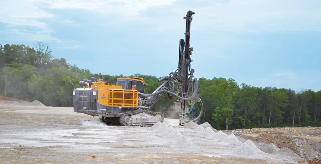
Production drilling in the construction aggregate industry is performed with percussive or rotary drills.
Each drilling mechanism has its own advantages, and the selection typically depends on hole diameter, bench height and ground conditions. Understanding the distinctions between drill types is essential for optimizing penetration rate, minimizing deviation and aligning the drilling program with the blasting goals.
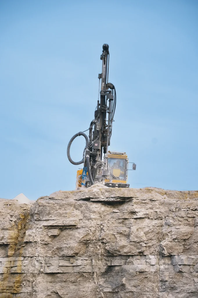
Percussive drilling is the most common method in aggregate operations. It includes both top hammer and down-the-hole (DTH) hammer systems. In a top hammer drill, the percussive energy is delivered from a hammer mounted above the rod string. As the hole deepens, additional drill steels are added, but the hammering continues from the top, which reduces efficiency and accuracy at greater depths. For shallow holes, typically under 50 ft., top hammers are fast and effective. They are generally used for hole diameters under 4 in.
However, top hammers become less efficient with depth or drill diameter. As the drill string lengthens, energy transmission degrades, alignment suffers and deviation increases. A 50-ft. hole with a top hammer may experience significant deviation from collar to toe – especially in jointed or variable ground – because the hammer is working through long lengths of steel. This deviation can result in inconsistent burdens, toe problems and uneven fragmentation.
DTH hammers, by contrast, place the hammering mechanism directly above the drill bit. Percussive energy is delivered at the bottom of the hole, and additional steels are stacked above the hammer as depth increases.
&uuid=(email))
This allows DTH rigs to maintain straighter holes and more consistent penetration rates – especially beyond 50 ft. DTH drilling is most often used for hole diameters over 4 in., though smaller configurations are available.
Rotary drills are less common in quarry production but are occasionally used in specific conditions. They function by grinding the rock with a rotating bit under high weight-on-bit – without percussive action. Rotary rigs are typically used for larger hole diameters, but they can be beneficial in very abrasive formations to extend life of bit or sandy formations where maintaining borehole integrity is critical.
In such conditions, rotary methods may outperform percussive drills in both hole quality and bit life.
In general, hole diameter and depth are the first decision points in selecting drill type. Top hammers dominate below 4 in., DTH hammers take over above that threshold and rotary drills occupy specialized use cases or very large diameter holes.
Of course, depth, rock conditions and structural variability also play major roles. A proper drilling plan starts by matching the tool to the application not just for speed, but for control and precision.
Drill bits and accessories
The performance of a drill is only as effective as the bit it turns and the components that support it.
While drill type sets the framework for penetration and energy delivery, bits, hammers, steels and accessories dictate how that energy interacts with the ground. In aggregate operations, where production volume is high and cost control is critical, selecting the right accessories and maintaining them properly can make the difference between steady performance and daily setbacks.
Bits come in multiple styles and configurations depending on ground conditions. Button bits are the most common across both top hammer and DTH drilling. Their wear resistance and predictable behavior make them the industry standard. Cross bits and chisel bits may be used in certain deposits or systems, as well, but they are less common today.
Bit size must align with hole diameter, but ground conditions also matter. Abrasive or hard formations accelerate wear, while soft or sandy zones can cause bit clogging or cleaning issues.
Bit wear is one of the most significant contributors to drilling cost. As the bit wears, penetration rate drops, deviation may increase and the hole quality declines. Bit changeouts should be planned and tracked – not just reactive. Sites that ignore wear rates often overextend bit life, losing far more in lost productivity than they save in delayed replacement.
PRO TIP
Use the right bit for the ground: Worn or mismatched drill bits reduce penetration and create crooked holes.
Hammers, particularly in DTH drilling, are also selected based on expected hole diameter and required energy. Larger hammers generally offer faster penetration and can handle tougher formations, but they require more air volume and fuel. Undersized hammers slow progress and increase wear.
Drill steels connect the rig to the hammer or bit and come in various diameters. In general, steels should be appropriately sized for the bit. Too narrow and they increase vibration and hole deviation; too thick and they reduce drilling efficiency and flushing of cuttings.
In top hammer systems, the length and straightness of each steel section also affect energy transfer and alignment.
Ultimately, accessory selection is not just about component matching; it is about maintaining hole quality, managing cost and ensuring the drilling program supports the broader goals of the blast. Each piece must be selected with the ground and the blasting objective in mind.
Hole diameter
Hole diameter is one of the most influential variables in the drilling and blasting process. It dictates the distribution of explosive energy, the configuration of the blast pattern and the overall cost and productivity of both drilling and loading operations.
In aggregate production, selecting the right hole diameter is not just a question of equipment capacity; it’s a design decision that impacts fragmentation, throw, heave and downstream performance.
Larger diameter holes generally result in lower drilling and blasting costs per ton. They reduce the total number of holes required in a given area, decrease the number of detonators and boosters needed, reduce the number of drills to meet tonnage requirements, and minimize drill realignment time. Loading is also faster, and fewer boreholes means less total work for the blaster.
From a production standpoint, larger holes can dramatically increase footage drilled per shift and, when placed on a larger pattern, substantially increase the tons of rock prepared to blast per shift.
Still, larger holes also carry tradeoffs. As hole diameter increases, so does the average size of fragmentation. If the stiffness ratio and pattern are not properly adjusted, oversized rock, poor heave or uneven muckpiles may result.
Larger holes distribute explosive energy across a broader area, which can become ineffective in highly jointed, weathered or weak rock masses. In these conditions, large holes often fail to fragment properly, and their wider spacing can create unbroken zones or excessive oversize.
Conversely, smaller diameter holes allow for tighter burden and spacing, better energy concentration and more uniform fragmentation – particularly in variable or fractured geology. They are more effective in breaking along and between structural features and are often necessary when targeting better fragmentation for sizing critical products like asphalt stone.
However, small diameter drilling is slower, requires more holes per shot and increases overall initiation costs.
Hole depth is also an important consideration. Most top hammer rigs lose efficiency beyond 50 to 60 ft. due to energy loss through the drill steel. Penetration rates drop, deviation increases and air pressure becomes insufficient for efficient flushing.
DTH rigs maintain better performance at depth, making them preferable for benches beyond this range. Hole depth must also be aligned with bench height and the desired blast geometry – especially when maintaining an effective stiffness ratio.
Ultimately, hole diameter and depth must be chosen in concert with geology, desired fragmentation, pattern geometry and available equipment. There is no universal rule – only tradeoffs between desired outcomes.
The goal is not to drill the biggest or fewest holes, but to deliver explosive energy in a way that matches the rock and supports the production goals of the site.
Pattern geometry
Drill pattern geometry defines how energy is distributed across the rock mass. While the hole diameter and depth control vertical energy application, the pattern – specifically the burden and spacing – controls how energy moves horizontally and how efficiently the rock breaks between holes.
The two most common drill patterns in construction aggregate operations are square and staggered patterns. In a square pattern, holes are aligned in both rows and columns, which simplifies layout and is generally faster to drill.
However, energy distribution can be less efficient – especially in irregular or jointed geology, where zones between holes may remain underloaded. In a staggered pattern, each row is offset from the one before it, improving energy overlap between holes and generally resulting in better fragmentation. Staggered patterns often produce more even muckpiles and reduce oversize, though they may increase layout and drilling time.
Pattern geometry is also influenced by geology. Highly structured or jointed rock may require reduced burden and spacing. Even in massive rock, seams or voids can disrupt energy transfer and create uneven results. While a typical blast may start with a base burden and spacing tied to hole diameter, adjustments must be made for localized conditions.
Occasionally, angled holes are used to better target toe zones, adjust for sloping benches or align the final face with geologic structure. However, angled drilling is less common due to slower drilling rates and greater deviation risk. Most operations default to vertical holes for speed and consistency, unless geology or design constraints require otherwise.
Ultimately, pattern geometry should not be fixed; it must be adapted to the rock, bench layout and blast goals. The best fragmentation comes from matching geometry to the reality in the ground.
Drilling accuracy and quality control
Precision in drilling is non-negotiable. Even the best blast design will fail if the holes are not drilled where, how and to the depth they’re intended.
Inaccurate drilling results in uneven burdens, misfires, poor fragmentation and dangerous flyrock. Quality control in drilling is not just about speed or footage; it is about accuracy, repeatability and adherence to design.
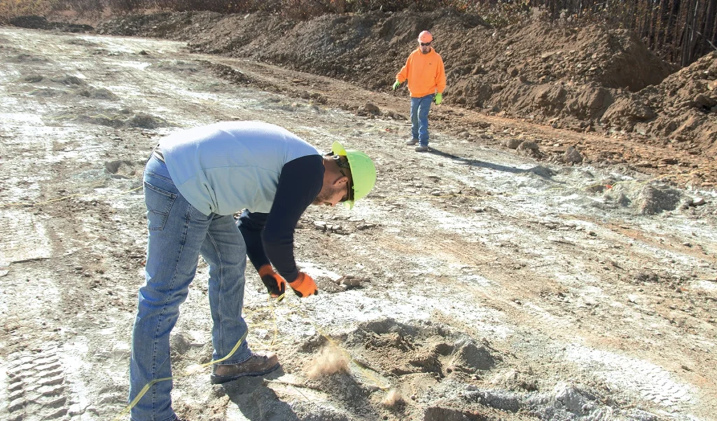
Hole layout is the first critical step. The best practice today is for the blaster or a designated technician to lay out the pattern using GPS-enabled survey equipment. These systems allow for precise placement of collar coordinates based on 3D terrain models, ensuring each hole is positioned exactly as intended relative to the bench geometry.
In many operations, 3D design data from blast modeling software is uploaded directly into GPS receivers for layout and stakeout. Advanced sites may also use lidar or photogrammetry to generate accurate digital terrain models for blast planning and layout.
Where GPS is unavailable, manual layout using a tape measure remains common. In these cases, a burden pole should always be used at the toe to verify burdens – particularly when working on irregular or sloped benches. Manual layout is more prone to error and must be double-checked for collar alignment and toe coverage.
&uuid=(email))
Once drilling begins, hole deviation becomes the primary concern. Deviated holes can result in excessive or insufficient burden, leading to oversize, flyrock or high toes. Top hammer systems are more prone to deviation due to energy loss through the steel string – especially at greater depths. DTH systems offer superior accuracy in deeper holes, as the hammering mechanism is located directly above the bit.
PRO TIP
Verify hole depths against the plan: Don’t rely on a driller’s “feel” – underdrilling leaves high toes and poor fragmentation.
QA/QC should include:
Planned versus actual depth. Holes must be drilled to the design depth; not simply until the driller “feels the bottom.” Overdrilling adds cost without benefit; underdrilling compromises fragmentation and floor control.
Collar location and verticality. GPS or manual layout must be verified before and after drilling. Slight collar shifts can significantly affect burden in tighter patterns.
Angle accuracy. For angled holes, consistent angle control is vital. Small errors here lead to large toe offsets at depth.
More advanced operations may use downhole survey tools to measure actual borehole path and confirm deviation.
Good drilling starts with good layout, but great drilling is achieved through constant validation. QA/QC must be integrated into every stage of the drilling process to ensure that design intent becomes reality on the bench.
Drill logs and structural feedback
The most overlooked – and yet most critical – component of a drilling program is the drill log. In today’s industry, many operations focus solely on speed, footage and cost per foot. But the true value of drillers lies not just in how quickly they can drill a hole, but in how accurately they can record what they encountered along the way.
A driller who cannot or does not properly log the structure of the rock mass is not just underperforming; they are compromising the entire blast.
Drill logs are the blaster’s only real-time tool for understanding subsurface geology. They provide essential feedback about what lies between the collar and the toe of each hole: the presence of seams, voids, bedding planes, mud zones or transitions in rock type or strength. This information is critical for making decisions about loading, timing, stemming and decking. Without it, the blaster is essentially firing blind.
Logging should capture:
- Penetration rate changes (indicating harder or softer zones)
- Drill chatter or vibration changes
- Loss of air return or water presence (often signaling voids or open seams)
- Bit deflection or hole collapse
- Material description from cuttings
This info does not require high-end software but discipline and field awareness. The best drillers can “read the ground” through feel and sound and reliably translate those cues into usable data. That data must be logged, preserved and handed off to the blaster for integration into the loading plan.
The economic value of good drill logs far outweighs any minor difference in cost per foot. A few cents saved on a driller who skips or fakes logging can lead to thousands of dollars in oversize, secondary breakage, vibration complaints or flyrock risk.
PRO TIP
Log ground conditions consistently: Drill logs aren’t paperwork – they’re the blaster’s map to avoid voids, seams and misfires.
At the organizational level, mine managers and foremen must set expectations: drill logs are not optional. They are part of the production record. Operations should require logs as part of daily reporting and incentivize drillers who consistently provide accurate and actionable data.
FULL HANDBOOK
Chapter 1: Industry Overview
Chapter 2: Geology & Site Selection
Chapter 3: Drilling & Blasting
Chapter 4: Excavating & Loading
Chapter 5: Hauling
Chapter 6: Crushing & Hydraulic Breaking
Chapter 7: Screening
Chapter 8: Washing & Classifying
Chapter 9: Conveying & Material Handling
Chapter 10: Loadout & Weighing
Chapter 11: Safety & Health
Use the page numbers to continue reading, or select a section / chapter above.